If the ground spoilers are not armed, they will automatically extend when:
FLIGHT CONTROL SYSTEM - The objective of the rotation law is to provide an homogeneous rotation for all possible weight, CG and configurations, while minimizing the risk of a tail strike. The rotation law is a pitch rate demand control law, providing tail strike protection.
The rotation law depends on the pitch rate, the tail clearance, the sidestick position.
The maximum achievable bank angle is:
The takeoff CG used for the pitch trim setting is provided by the FQMS, based on the ZFCG entered by the flight crew in the FMS Fuel & Load page, and on the fuel distribution. It is displayed in the permanent data of the system display.
In the TAKEOFF panel of the FMS PERF page, the flight crew enters the THS position for takeoff, based on the takeoff CG of the loadsheet. This input is not used for automatic pitch trim setting. It is used to trigger the FCTL PITCH TRIM-FMS-CG DISAGREE caution, if necessary.
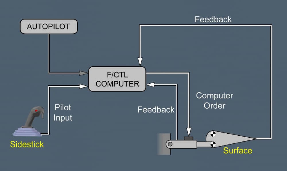
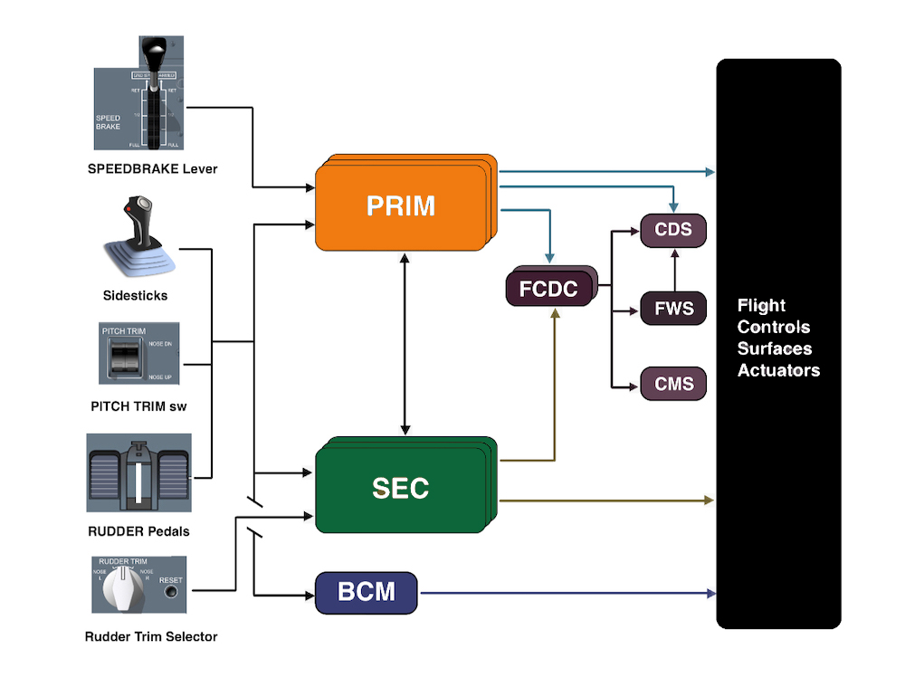
Six flight control computers (3 PRIMs and 3 SECs) process pilot and autopilot inputs.
One computer of any type (PRIM or SEC) is able to control the aircraft and ensure safe flight and landing.
AUTOMATIC PITCH TRIM SETTING - The pitch trim is automatically set for takeoff:
The pitch trim setting for takeoff is function of the takeoff CG.
TRIMMABLE HORIZONTAL STABILIZER (THS) - The THS has two electric motors, a screwjack and a ball nut.
When the Flap Load Relief System (FLRS) is active:
Whe the autopilot is engaged the sidesticks are locked in the neutral position. If a flight crewmember applies on a sidestick a force above a given threshold:
The following surfaces are fitted with an EHA:
Advertisement
The inner ailerons have:
The speed brake and ground spoiler functions use:
In the event of the temporary loss of all flight computers (PRIMs and SECs), the Backup Control Module (BCM) provides aircraft control and stability.
In alternate law the pitch, roll and yaw controls are similar to controls in normal law. All protections are indicated as lost. However, protections are still available but, depending on the failure, may not be as efficient as in normal laws.
All the spoilers and ailerons are also used as ground spoilers. When a spoiler fails on one side:
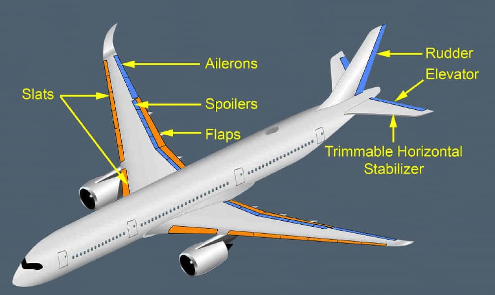
On each wing, the 2 ailerons and the two largest spoilers control the aircraft in roll.
On each wing, the 2 ailerons and the spoilers 3 to 7 control the aircraft in roll.
SIDESTICK PRIORITY LOGIC - A flight crew member can deactivate the other sidestick and take full control, by pressing and keeping pressed the sidestick pb. To deactivate the other sidestick, the flight crewmember must press their sidestick pb for _____.
The other sidestick is permanently deactivated, until any flight crewmember presses their sidestick pb.
The slat alpha speed lock function inhibits slats retraction to zero at a high Angle-Of-Attack (AOA), and or at a very low speed.
The slats and flaps control units use the AOA, or the airspeed, to inhibit slats retraction. The ADIRUs provide this information to the slats and flaps control units.
In direct law, there is:
DIRECT LAW & PITCH CONTROL - The speed is limited to:
Advertisement
The Flap Load Relief System (FLRS) limits the loads on the flaps, in the case of a VFE exceedance.
The FLRS automatically retracts the flaps at VFE + 2.5 kt (i.e. before the overspeed warning triggers at VFE + 4 kt).
The stabilizer has ____ electric motors.
LATERAL CONTROL - In direct law, all protections are lost.
SIDESTICK PRIORITY LOGIC - At all times, only one flight crew member should fly the aircraft. However, if both flight crew members use their sidesticks simultaneously, their orders are algebraically added.
The flight control laws limit the combined order to the equivalent of the full deflection of one sidestick. In this case a DUAL INPUT callout is triggered.
The flight control system is a fly-by-wire system. The flight control surfaces are:

The surfaces are actuated by one or both hydraulic systems, or by an independent hydraulic source (EHA-EBHA)
In normal and alternate laws, regardless of the pilot's input, the flight control computers prevent excessive maneuvers and any exceedance of the safe envelope in pitch, roll and yaw.
This is valid in normal law only.
In manual flight, the normal law provides rudder control from the rudder pedals, to achieve a sideslip which is proportional to the pedal deflection, independent of the aircraft speed. For a given sideslip angle, the aircraft will stabilize at a given roll angle. Below 100 ft, the aircraft will try to maintain wings level, independently of sideslip demand.
This is to assist pilot control in roll during the decrab phase in the case of crosswind conditions.
FLIGHT LAW - The normal law in flight is a load factor demand law with auto trim and full flight envelope protection.
In manual flight, the normal law provides elevator and pitch trim control from the sidesticks, to achieve a load factor which is a function of the sidestick deflection, independent of the aircraft speed.
When the bank angle is less than ______ the normal law maintains a constant bank angle when the sidestick is at neutral (neutral spiral stability) and rovides automatic pitch trim (turn compensation).
The Wing Tip Brakes WTBs mechanically lock the slats(flaps) transmission shaft, when both SLAT(FLAP) CTL detect:
The WTBs also mechanically lock the flaps transmission shaft when both FLAP CTL detect a flap disconnection. When a WTB is set, it cannot be unlocked in flight. Maintenance action is required.
Advertisement
The aim of the Load Alleviation Function (LAF) is to reduce the fatigue and static loads on the wing. The LAF is part of the normal pitch law and can also be available in alternate law.
GUST LOAD ALLEVIATION - The GLA reduces the loads in the case of turbulence. The GLA reduces the lift of the outer wing.
The GLA is active above 200 kt. The deflection of the ailerons depends on the variation of the angle of attack during the last 5 s. The ailerons can be deflected up to a maximum of 12 degrees upwards. Flight crew roll orders have priority on GLA.
Roll control uses:

The roll function of the spoilers is inhibited _____, when the spoilers are used for the ground spoiler function. Roll control is available through ailerons.
ACTIVE DIFFERENTIAL GEARBOX (ADGB) - The flaps systems can control the inner and outer flaps independently to enable a Differential Flap Setting (DFS).
ADHF CONTROL - In configurations 1 or 2, the Adaptive Droop Hinge Function (ADHF) improves the aerodynamic performance of the wing by controlling the gap between the spoilers' trailing edge and the flaps' leading edge
This is valid in configurations 1, 2, 3 and FULL. The spoilers are deflected downward to control this gap.
When the autopilot is engaged, the RUDDER TRIM selector is not active.
On ground, when hydraulic power is available, the reservoir of the Electro-Hydrostatic Actuators (EHA) is automatically refilled, if needed. The hydraulic fluid is taken from the green hydraulic system.
The hydraulic fluid is taken from the hydraulic systems (green or yellow).
During a rejected takeoff the ground spoilers fully extend when the thrust levers are at idle and the speed is greater than ______.
If the ground spoilers are not armed, they will automatically extend when the reversers are selected and the speed is greater than 72 kt.
BACK-UP CONTROL - In the unlikely event of the loss of all flight control computers (PRIMs and SECs), the backup control provides control and stability of the aircraft. The backup control controls the inner ailerons, the rudder and the elevators.
Advertisement
After landing, the pitch trim will move to 0.8 deg. (maintenance position) when the speed goes below 30 kt.
The authority of the rudder trim is _____ of the maximum rudder deflection.
The outer ailerons are not deflected up or down _____.
The sidesticks are springloaded to neutral.
During a touch and go, the pitch trim will automatically move to the takeoff position, based on the aircraft CG.
The normal flight law is available in flight from _____ . (The normal flight law is gradually phased-in during 5 s, 5 s after liftoff).
The transition to the flight law is reduced to 1 s, if the angle of attack protection, or the pitch attitude protection is active.
In normal operation, one PRIM computer is the master (usually PRIM 1) and computes the orders.
Each flight control actuator is connected to one PRIM and one SEC. In normal operation, the PRIMs control the actuators. In the case of impossibility for the PRIM to control its actuators, the associated SEC takes over.
On ground, after the first engine start, the sidestick position indication appears on both PFDs. It corresponds to the sum of both sidestick orders, except if a sidestick has taken the priority. The indication disappears ______
The three PRIMs:

