Main electric trim has 2 speed modes : high & low speed.
Elevator system feel is provided by the elevator feel computer. This computer receives inputs of:
In the event of hydraulic Systems A & B fail, ailerons, elevators, and rudder can be operated with the Standby system.
During a steady right-handed turn on the ground, correct indications of the Yaw Damper indicator would be?
What is number of ground spoilers on each wing?
Leading Edge devices are normally operated by ______
Speed Trim Failure (SPEED TRIM FAIL) Light - If illuminated (amber) this indicates a:

In addition to Hydraulic System A & B, the rudder can also be powered by the Standby Hydraulic System through the:
During a normal landing, flight spoilers & ground spoilers will always extend simultaneously.
The Power Transfer Unit provides an alternate source of power for the Autoslat System if:
Advertisement
The Speed Trim System (STS) operates most frequently during takeoffs & go-arounds. Conditions for speed trim operation are:
Concerning Mach Trim operation, FCCs use Mach information from the ADC / ADIRU, to compute a Mach trim actuator position whih repositions the elevator feel & centering unit, which adjusts the control column neutral position (column will not move).
The column will move
The number of slats located on each wing are:
The Flap/Slat Electronics Unit (FSEU) provides:
The speedbrake lever will move forward and all spoilers will retract if either thrust lever is advanced after landing.
Mach Trim system corrects for Mach tuck by moving stabilizer up.
It moves elevators up (not the stabilizer)
Yaw damper inputs (main or standby) can be overriden:
? With a loss of both system A & B, the elevator FEEL DIFF PRESS light will illuminate:
If wheel spinup is not detected on landing with the speed brake armed the flight spoilers will deploy automatically :
If the spoilers become jammed:
Advertisement
The trailing edge flaps are at 15 units. The correct indication on the aft overhead panel for the leading edge devices is:
If the SPEEDBRAKES EXTENDED light is illuminated in flight. It indicates:
Landing flap 40 selected and in position. An IAS of 178kts is flown due to a highwind gust. Would you expect:
! When the flaps are set at 40, the TE flaps:- retract to 30 if airspeed exceeds 163 knots- re-extend when airspeed is reduced below 158 knots.When the flaps are set at 30, the TE flaps:- retract to 25 if the airspeed exceeds 176 knots- re-extend when airspeed is reduced below 171 knots.
Dual AILERON trim switches, located on the aft electronic panel, must be pushed simultaneously to command trim changes. The trim electrically repositions the aileron feel and centering unit, which causes the control wheel to rotate and redefines the aileron neutral position.
To operate the Feel system, the Elevator Feel Computer uses:
The system operates normally even with only one hydraulics system remaining
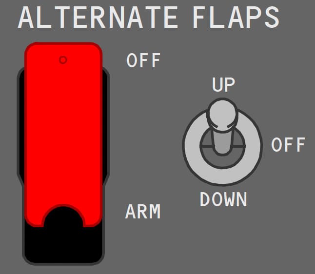
The ALTERNATE FLAPS Master Switch:
Why are mechanical gates installed on the flap selector unit.
During descent from altitude you need to decrease your aispeed by using your speed brakes. What is the correct position of the SPEED BRAKE LEVER.
If the flight crew selects the ALTERNATE FLAPS to the ARM position:
The Speed Trim System (STS) is a speed stability augmentation system designed to improve flight characteristics during operation with a low gross weight, aft center of gravity and high thrust when the autopilot is not engaged.
The STS monitors inputs of stabilizer position, thrust lever position, airspeed and vertical speed and then trims the stabilizer using the autopilot stabilizer trim.Remember that the SPEED TRIM FAIL amber light is often illuminated when you arrive at the aircraft. It is only due to the Inertial Vertical Speed Indicator which is not powered by the ADIRUs (IRS selectors OFF): the STS receives invalid inputs.
Advertisement
The elevator transfer mechanism allows:
Roll control is provided by the ailerons, assisted by the _____
The flap load relief system is operational at:
The amber LE FLAPS TRANSIT light:
What is the correct flap setting for a jammed stabilizer landing?
The airspeed range for trim operation is:
The primary flight controls consist of rudder, ailerons and ______
During an ALL FLAPS UP LANDING, the speed to be maintained is:
What is the maximum flap extension altitude?
Loss of Hydraulic System B pressure does not cause illumination of the amber YAW DAMPER light or yaw damper disengagement.

Advertisement
What is the number of flight spoilers located on each wing?
The flight spoilers rise on the wing with up aileron and remain faired on the wing with down aileron. When the control wheel is displaced more than approximately ____ degrees, spoiler deflection is initiated.
The Autoslat system:
At what flap setting(s) should the leading edge slats be in the FULL EXTEND position?
The flight control computers use Mach Information from the _____ to compute a Mach trim actuator position.
With the loss of hydraulic system B, (system A operating normally):
The FEEL DIFF PRESS light indicates:

Excessive differential pressure can be caused by erroneous activation of the Elevator Feel Shift module.
The amber FEEL DIFF PRESS light illuminates when the:
The SPEED BRAKE DO NOT ARM light indicates that the speedbrake is not usable.
A Mach Trim system provides speed stability at the higher Mach numbers.Mach trim is automatically accomplished above:
Advertisement
What do the MACH TRIM FAIL, SPEED TRIM FAIL & AUTO SLAT FAIL lights have in common? + All of the above.
Extending the flaps to flaps 15 using ALTERNATE FLAPS takes approximately _______
Elevator Feel provides simulated aero forces using airspeed from elevator pitot & stabilizer position.
The feel is transmitted to the control columns by the elevator feel & centering unit.